How does it work......roughly
In protected mode, surprisingly, we still use segments (actually we can not disable segmentation feature), every segment can contain a memory space up to 4GB.
Segment is presented by the register called selector, which is the segment register in real mode like CS, DS, etc..
Let's put it in this way: in a memory segment which is described by selector CS = 0x8, we may have the ability to access 0~4G-1 bytes directly,
I said "may" just because we can choose how large the segment is, not a fixed 64KB in real-mode.
I have mentioned segments are described by selectors, that is not precise, actually a selector is kind of an index into a segment descriptor entry in system tables which store
the information about all segments that the system can use. Those information includes where the segment starts, the length of the segment called limit and the type and privilege of the segment etc.
To access a location in memory, a segment selector and an offset must be supplied in the format selector:offset, just like it is in real mode.
For example, we can let selector 0x8 points to a descriptor which refer to a segment starts at B8000, then we can use 8:00000000 to access the first byte of video memory which affects the first character on screen.
There are three different type of tables in system: GDT (global descriptor table), LDT (local descriptor table), IDT (interrupt descriptor table).
Once the processor is in protected mode, all memory accesses pass through GDT or LDT.
We are going to use GDT in this tutorial, GDT can be shared by all tasks as its name implied. We are going to use one data segment and one code segment.
Here is the format of the code/data descriptor, one descriptor is 64-bit long,
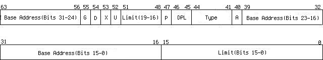
| Limit(Bits 15-0) | lower 16-bit limit |
| Base Address(Bits 15-0) | lower 16-bit base address |
| Base Address(Bits 23-16) | middle 8-bit base address |
A
| access information, whether it was read from(=0) or written to(=1) by the last access |
| Type | | Bit 41 | for date/stack segment it can be written to (=1)
for code segment it can be read from(=1) |
| Bit 42 | for date/stack segment it indicates expansion direction, it grows downside(=1)
for code segment, confirming(=1) |
| Bit 43 | whether it is code segment(=1) or it is a date/stack segment(=0) |
| Bit 44 | must be 1 for code/data segment |
|
| DPL | descriptor privilege level, we are going to use 0-kernel privilege and 3-user privilege in Skelix |
| P | whether the segment is present. It is always 1 in this tutorial |
| Limit(Bits 19-16) | middle 8-bit limit |
| U | user defined |
| X | not used |
| D | whether handle instructions and data as 32-bit(=1) or 16-bit(=0) |
| G | whether the limitation use unit 4K or 1 byte |
| Base Address(Bits 31-24) | higher 8-bit base address |
As we can see, a descriptor actually includes a 32-bit base address and a 20-bit limit and some attributes, the 32-bit base address indicate where the segment starts,
and the 20-bit limit indicates the length of the segment. However, a problem comes up, 20-bit limit can only represent 2^20 = 1MB memory, to access a 4GB memory space,
descriptor uses G bit to indicate whether the limit use 4K or 1 byte for one unit, that means if G bit is set then we get 2^20*4K = 4GB memory, if it is unset then we only use a memory space under 1MB.
Privilege protection is how the protected mode gets its name from, to explain how it works we have to take a look at the selector. As mentioned above, selector is an index of a descriptor table,
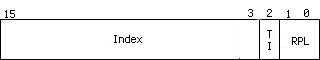
| RPL | requester privilege level |
| TI | whether it is an index into GDT(=0) or LDT(=1) |
| Index | index into the table |
Program's privilege level(PL) is equal to the RPL field in the selector in CS register, it is equal to the current privilege level(CPL) in general.
Programs at lower privilege level(PL) can not access data segment which at higher level and can not execute certain instructions.
When a selector is loaded to an segment register, the processor will check the CPL and the RPL then make the lower privilege level as effective privilege level (EPL),
then compare the EPL with DPL in descriptor, if EPL has higher privilege then the access is allowed @_@b. It works roughly in that way, actually it also checks the write/read attribute, present attribute etc.
As we can see in selectors, the Index field is 13-bit long, so it can present 2^13=8192 (#Bug 003: Arshad Hussain pointed out
my original calculation was wrong) descriptors in one table.
There is only one GDT in system but each process can have their own LDT. Processor reserves the first descriptor of the GDT, it should be set to zero and can not be used based on manuals.
However, out of topic, it does seem can be used safely, I seemed to remember I read some code about it somewhere...
Entering Protected Mode
We boot Skelix from a floppy disk in last tutorial, which gives us the ability to execute code in real-mode. To enter the protected mode, a mode switch must be performed and we will not let Skelix
go back to real-mode again. Before entering the protected mode, there are some preparations have to be done, a GDT has to be created at first,
02/bootsect.s
gdt:
.quad 0x0000000000000000 # null descriptor
.quad 0x00cf9a000000ffff # cs
.quad 0x00cf92000000ffff # ds
.quad 0x0000000000000000 # reserved for further use
.quad 0x0000000000000000 # reserved for further use
There are 5 entries in GDT, we are going to use first three of them. The first one is the null descriptor as Intel demanded, the second descriptor is for CS segment, let's check it out from higher bits to lower bits,
| Bits 15-0 | FFFFh | lower 16-bit limit |
| Bits 39-16 | 000000h | lower 24-bit base address |
| Bit 40 | 0b | just set it to 0 |
| Bit 41 | 1b | readable |
| Bit 42 | 0b | confirming |
| Bit 43 | 1b | code segment |
| Bit 44 | 1b | must be 1 |
| Bits 45,46 | 00b | kernel privilege |
| Bit 47 | 1b | presented |
| Bits 48-51 | Fh | middle 8-bit limit |
| Bits 52 | 0b | just set it to 0 |
| Bits 53 | 0b | just set it to 0 |
| Bits 54 | 1b | 32-bit instructions and data |
| Bits 55 | 1b | use 4KB unit for limit |
| Bits 63-56 | 00h | higher 8-bit base address |
The second descriptor refer to a presented code segment which starts from 00000000, the limit is FFFFF*4K = 4G bytes works at kernel privilege, all data and instruction in this segment should be handled as 32-bit.
The third descriptor is used for date and stack segment, the difference exists at Bit 43, it is set to 0 means it is a data segment.
Now, we got GDT ready, but how can the processor finds this table? Compare to real-mode, there are several new registers that we can use in protected mode, we are going to use GDTR,
it is loaded by instruction LGDT, GDTR is 48-bit long, it is grouped with one WORD indicates the length of GDT in byte and one DWORD indicates the start address of GDT.
Before go any further with this tutorial, some contants we are going to use are defined in file 02/include/kernel.inc,
.set CODE_SEL, 0x08 # code segment selector in kernel mode
This selector is 00001000 in binary, it refers to the second descriptor in GDT, that is the CS segment descriptor.
.set DATA_SEL, 0x10 # data segment selector in kernel mode
.set IDT_ADDR, 0x80000 # IDT start address
We set all system information at a fixed address, IDT (will be introduced in next tutorial) is the beginning of all informations.
.set IDT_SIZE, (256*8) # IDT has fixed length
.set GDT_ADDR, (IDT_ADDR+IDT_SIZE)
# GDT starts after IDT
We use GDT_ADDR instead of the address of gdt because we are going to move all system tables to a fixed address before we enter the protected mode,
and the 7C000 area will be overwritten.
.set GDT_ENTRIES, 5 # GDT has 5 descriptors
# null descriptor
# cs segment descriptor for kernel
# ds segment descriptor for kernel
# current process tss
# current process ldt
We are going to use 5 GDT descriptors in Skelix, we have introduced the first three, the last two will be explained in the future.
.set GDT_SIZE, (8*GDT_ENTRIES)
# GDT length
One descriptor is 8 bytes long, so the total GDT is 8*GDT_ENTRIES bytes long.
.set KERNEL_SECT, 72 # Kernel lenght, counted by sectors
Because kernel size is larger than one 512-byte secter, so we set a kernel length to let boot code know how many sectors it should read from disk.
.set STACK_BOT, 0xa0000 # stack starts at 640K
The kernel stack starts at address 640KB and goes downwards, because the space above 640KB is used by some other hardwares.
Let's take a look at the boot sector code, 02/bootsect.s
.text
.globl start
.include "kernel.inc"
.code16
start:
jmp code
gdt:
.quad 0x0000000000000000 # null descriptor
.quad 0x00cf9a000000ffff # cs
.quad 0x00cf92000000ffff # ds
.quad 0x0000000000000000 # reserved for further use
.quad 0x0000000000000000 # reserved for further use
Loading constants from 02/include/kernel.inc and set GDT.
gdt_48:
.word .-gdt-1
.long GDT_ADDR
code:
xorw %ax, %ax
movw %ax, %ds # ds = 0x0000
movw %ax, %ss # stack segment = 0x0000
movw $0x1000,%sp # arbitrary value
# used before pmode
Puts the stack top at an arbitrary value, just keep it from overwriting the boot sector code at 7C00.
## read rest of kernel to 0x10000
movw $0x1000,%ax
movw %ax, %es
xorw %bx, %bx # es:bs destination address
movw $KERNEL_SECT,%cx
movw $1, %si # 0 is boot sector
rd_kern:
call read_sect
addw $512, %bx
incw %si
loop rd_kern
Reads the rest of kernel to memory 0x10000 temporarily, they are going to be moved to address 0 after entering protected mode. The function read_sect is hard to be explained in details,
and I'm not going to do that, you can read it for your pleasure :)
CLI disables maskable hardware interrupts because we are entering protected mode, all interrupts work in real mode will not be available in protected mode.
## move first 512 bytes of kernel to 0x0000
## it will move rest of kernel to 0x0200,
## that is, next to this sector
cld
movw $0x1000,%ax
movw %ax, %ds
movw $0x0000,%ax
movw %ax, %es
xorw %si, %si
xorw %di, %di
movw $512>>2,%cx
rep
movsl
Moves the first 512 bytes of newly read kernel code to 0x0000, those kernel code are generated by 02/load.s, which will be introduced in a while. This 512-byte code reads rest
of the kernel to 0x0200, just follows the first 512 bytes in memory. In this tutorial, 02/load.s does nothing but displays "Hello World!" on screen.
xorw %ax, %ax
movw %ax, %ds # reset ds to 0x0000
## move gdt
movw $GDT_ADDR>>4,%ax
movw %ax, %es
movw $gdt, %si
xorw %di, %di
movw $GDT_SIZE>>2,%cx
rep
movsl
Moves GDT to a predefined address GDT_ADDR for further usage.
enable_a20:
## The Undocumented PC
inb $0x64, %al
testb $0x2, %al
jnz enable_a20
movb $0xdf, %al
outb %al, $0x64
This method of enabling A20 is introduced in book "The Undocumented PC". A20 is a bus gate in keyboard controller (don't ask me why Intel puts it there), after power-up it is closed,
enabling it gives us the ability to access the memory beyond 1MB.
Loading GDT descriptor into register GDTR.
## enter pmode
movl %cr0, %eax
orl $0x1, %eax
movl %eax, %cr0
By setting the PE flag in control register CR0 at bit 0, we switched the processor to protected mode. Surprisingly easy, right?
Only if we ignore those preparations.
Now we are in protected mode, but before doing anything, we need a far jump to flush out the prefetched pipeline, because there are 16-bit instructions in it
and we are going to to use 32-bit operands and instructions from now on. This ljmp makes processor start to execute the code at address 0 with selector 0x8, which is
the second descriptor in GDT. Note that we have moved the first 512 bytes of kernel code to this address.
## in: ax: LBA address, starts from 0
## es:bx address for reading sector
read_sect:
pushw %ax
pushw %cx
pushw %dx
pushw %bx
movw %si, %ax
xorw %dx, %dx
movw $18, %bx # 18 sectors per track
# for floppy disk
divw %bx
incw %dx
movb %dl, %cl # cl=sector number
xorw %dx, %dx
movw $2, %bx # 2 headers per track
# for floppy disk
divw %bx
movb %dl, %dh # head
xorb %dl, %dl # driver
movb %al, %ch # cylinder
popw %bx # save to es:bx
rp_read:
movb $0x1, %al # read 1 sector
movb $0x2, %ah
int $0x13
jc rp_read
popw %dx
popw %cx
popw %ax
ret
read_sect reads disk sectors, ES:DX indicates the destination memory address,
SI indicates which sector is going to be read, like 0 means the boot sector, CX indicates how many sectors are
going to be read. If you really want to read it through, then enjoy your slow death :)
.org 0x1fe, 0x90
.word 0xaa55
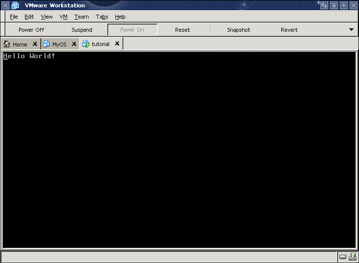
Hello World Comes Back
After entering protected mode, all general and segment registers still hold the values they had in read mode and the code begins with CPL 0, that means we can execute any instructions and access any ports
and memory addresses. 02/load.s will be executed at address 0.
.text
.globl pm_mode
.include "kernel.inc"
.org 0
Tell the loader, this code will start executing at logical address 0, in this case the physical address is 0 as well.
pm_mode:
movl $DATA_SEL,%eax
movw %ax, %ds
movw %ax, %es
movw %ax, %fs
movw %ax, %gs
movw %ax, %ss
movl $STACK_BOT,%esp
We load all date and stack segment registers with selector 0x10, refers to the third descriptor in GDT, RPL is also 0. This step is extremely important, all segment registers
must refer to valid descriptors.
cld
movl $0x10200,%esi
movl $0x200, %edi
movl $KERNEL_SECT<<7,%ecx
rep
movsl
Move the rest of kernel right after 02/load.s. (#Bug 1: Song Jiang has pointed out that we should move KERNEL_SECT-1 sectors
instead of KERNEL_SECT because we have moved the first kernel sector to 0x0000 and he is correct. Since KERNEL_SECT is just an arbitrary value that big enough so we can read whole kernel into memory,
keep using KERNEL_SECT won't cause any problem).
movb $0x07, %al
movl $msg, %esi
movl $0xb8000,%edi
How exciting, we can use 32-bit address now!!
1:
cmp $0, (%esi)
je 1f
movsb
stosb
jmp 1b
1: jmp 1b
msg:
.string "Hello World!\x0"
A picture says thousands words, allow me to make all those movements clear, at first boot sector was loaded at 00007C00, it sets the stack top at memory 00001000,
then it read the rest of kernel to memory 00010000. After that, moves the first sector of kernel which contains the code generated by 02/load.s to address 0.
Figure 1 illustrates the memory image.
Figure 1 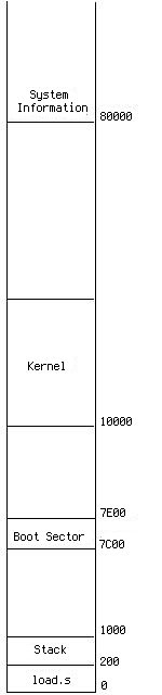 | Figure 2 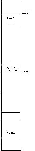 |
After entering the protected mode, 02/load.s move the rest of kernel right after it and set stack at address A0000. Figure 2 illustrates the memory image.
At last, let's check out the Makefile,
02/Makefile
-I option tells assembler to find kernel.inc in folder include.
LD=ld
KERNEL_OBJS= load.o
Kernel only includes the module assembled from 02/load.s at this moment.
.s.o:
${AS} -a $< -o $*.o >$*.map
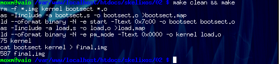
all: final.img
final.img: bootsect kernel
cat bootsect kernel > final.img
@wc -c final.img
bootsect: bootsect.o
${LD} --oformat binary -N -e start -Ttext 0x7c00 -o bootsect $<
kernel: ${KERNEL_OBJS}
${LD} --oformat binary -N -e pm_mode -Ttext 0x0000 -o $@ ${KERNEL_OBJS}
@wc -c kernel
Kernel code starts at address 0x0000.
clean:
rm -f *.img kernel bootsect *.o
Generating the final.img
Hello world comes back!