A processor organizes and accesses memory as a 8-bit sequence, every memory byte can be located by an unique address, which called physical
address, the range of the address can represent is called an address space
There are two common ways for memory addressing: segmentation and paging, and they both are used in Skelix.
Segmentation is familiar to us. Going back to the good old days: DOS era. Because all registers are 16-bit long at that time,
so we can only access a 2^16 = 65536 bytes long memory space directly. 64KB was not enough for greedy programmers. Intel uses two 16-bit registers as
Segment:Offset pair to represent a physical address, it uses a 16-bit segment register to represent a memory segment and another 16-bit register to represent
an offset in this segment. It sounds so great that this scheme not only keeps our code, data and stack in separate segments and keep them from mingling with each other,
but also give us the ability to access a 2^16*2^16 = 4G large memory space. It is too good to be true, and it is not.
Well, it is a bit tricky, the segment register has to be shifted 4-bit to the left at first, then the value of offset register is added to it.
For example, pair 7C00:0189 gives us a physical address 7C189 instead of 7C000189. Note here all memory addresses are given in hexadecimal,
7C000
+ 0189
-------
7C189
Clearly, the largest value it represents is FFFF:FFFF
FFFF0
+ FFFF
------
10FFEF
It is 1M + 65519 bytes, because 80386 uses a 20-bit memory address bus (it will be discussed in the following tutorial),
so the exceed 65519 byte memory space are wrapped around to physical address 0. For example address 100010 is mapped to address 10,
accessing 100010 is the same as accessing address 10.
The other problem about this scheme is there are different ways to refer to the exact same physical address, like 07C0:0000 and 0000:7C00
both represent the physical address 00007C00.
Another scheme for memory addressing is linear address scheme, 32-bit linear address is used in this scheme, it will be discussed in details
in later tutorial.
Booting Process
After power-up or RESET, an initialization is performed on processors, it sets registers to a known state and
place processors in real-mode. Then the processor will execute the instruction at physical address FFFFFFF0 which usually is a far JMP
which sets by EPROM. You may wonder how segment:offset pair can represent a physical address FFFFFFF0, actually there is an invisible part in CS
register, it stores a base address FFFF0000, and IP has value FFF0 during reset, which gives a physical address FFFF0000+FFF0 = FFFFFFF0. That is where BIOS initialize buses, ports etc
Once BIOS finishes the initialization, it tries to load the operation system. Because BIOS has absolutly no idea of what kind of OS you are using,
it just load the first section of the bootable disk into a prefefined location, that is, physical address 00007C00. Instructions start at 00007C00 should create
a proper environment for specific OS.
To sum up, we need a 512-byte sector on booting disk, and BIOS requires it ends with AA55, which is a flag indicates this sector is a valid boot sector.
Skelix boots from a floppy disk.
You should keep in mind that at startup, the processor is in real-mode and uses segment:offset pair to access a 1MB memory space without any privilege protections.
We are allowed to use BIOS interrupts at this stage.
First Cry
Let's go through our first code snippet,
01/first.cry/bootsect.s
.text
.globl start
.code16
.text marks the start of code section.
.globlstart tells the assembler that start is an external symbol.
GCC uses 32-bit operands and addresses by default, .code16 tells it to use 16-bit operands and addressing mode.
start:
jmp start
A busy loop. That's it.
.org 0x1fe, 0x90
.word 0xaa55
.org0x1fe, 0x90 indicates filling the gap between our busy loop to address 1FE (510 in decimal)
with hexadecimal 90 (assembly instruction NOP which does nothing). Word AA55 will be writen at the end of this 512-bit sector,
as we mentioned above, it is the required flag for a bootable sector.
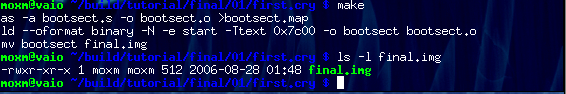
Now we have the first source code file, we have to "make" it work. To get it done automatically, a Makefile is needed. I am not going into details about how
to write a Makefile, you can find it on internet. Compiler options are what I am gong to focus on.
01/first.cry/Makefile
AS=as
LD=ld
as and ld are assembler and linkers that GCC toolchain uses.
--oformat binary means GCC should generate a raw flat binary file without header and other informations, sort of linke .com file in DOS.
Without this option, ld uses ELF format by default (actually it depends on your system settings), and BIOS has no idea what is an ELF file.
We may not need -N option in this code, but for the convenience of furture programming. It makes the text section to be readable and writable,
because I do not distinguish the text section and data section, and there will be some write actions in later tutorail.
-e start names an entry point, it tells the linker that the code should be executed at start symbol.
-Ttext 0x7c00 makes the text section has a base address 7C00 which is the start address of boot sector in memory. An offset 7C00 will be added
to all addresses in text section. For example, start symbol will have address 7C00 and that ending flag AA55 will be 7C00+1FE = 7DFE.
After "making", we should get a image file final.img, which should be exact 512-byte long.
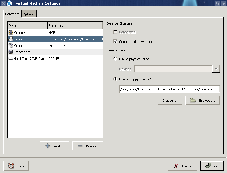
Please create a virtual machine in VMWARE like this one,
The important part is it should have 4MB memory and an 100MB IDE hard driver at 0:0. These value is hard coded in my source code to simplify my source code by getting
rid of hardware detection.
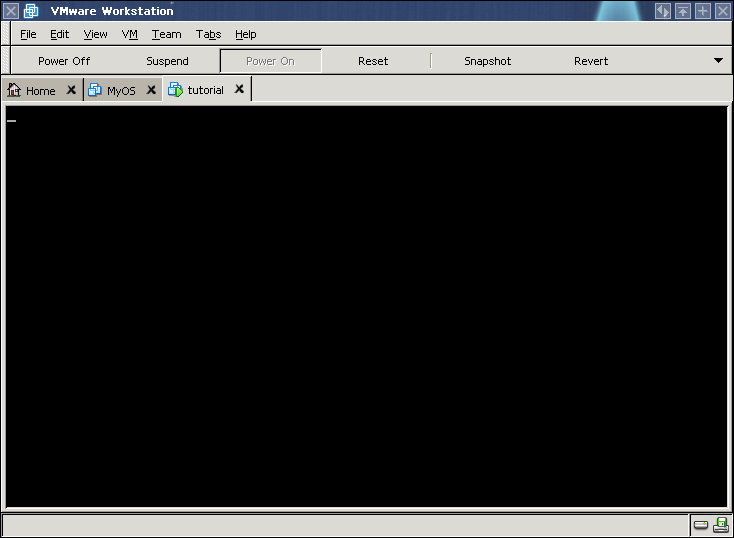
Now load final.img as the floppy image and let VMWARE boot from floppy disk first. Then power on this virtual machine, you can see absolutly nothing...
That is correct, because we just let it keep jumping.
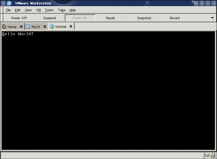
Hello World!
Okay, I have to admit that program in First Cry is not funny, so in this section we are going to let it perform "Hello World" ceremony.
01/hello.world/bootsect.s
.text
.globl start
.code16
start:
jmp code
msg:
.string "Hello World!\x0"
code:
movw $0xb800,%ax
movw %ax, %es
xorw %ax, %ax
movw %ax, %ds
Filling segment registers DS and ES with right values, register ES refer to segment B800,
as I mentioned above, it locates the memory space starts from B8000, which is the video memory for color graphics adapter. Screen directly reflects the change in this memory area,
for example in a 80x25 screen, the first character at position 0x0, it refers to memory address B8000, and its color attribute refers to address B8001. If we change the content
at address B8000 to 0x31, which is letter '1', and B8001 to 0x07, then we can see a black background and white foreground letter '1' on the top left corner on screen.
movw $msg, %si
xorw %di, %di
cld
movb $0x07, %al
1:
cmp $0, (%si)
je 1f
movsb
stosb
jmp 1b
Fills in B8000 area with "Hello World!" string and corresponding color attribute, which is the value 7 stores in AL, it gives a black background and white foreground.